Installing MacBook Unibody Hard Drive Cable
This guide will show you how to remove the hard drive cable from your laptop.
Tools used in this guide : Phillips #00 Screwdriver , Spudger
Parts relevant to this guide : MacBook Unibody Hard Drive Cable

Step 1 — Access Door
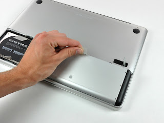
With the case closed, place the Unibody top-side down on a flat surface.
Depress the grooved side of the access door release latch enough to grab the free end. Lift the release latch until it is vertical.

Step 2
The access door should now be raised enough to lift it up and out of the Unibody.
Step 3 — Battery
Be sure the access door release latch is vertical before proceeding.
Grab the white plastic tab and pull the battery up and out of the Unibody.

Step 4 — Lower Case
Remove the following eight screws securing the lower case to the chassis:
One 3 mm Phillips screw.
Three 13.5 mm Phillips screws.
Four 3.5 mm Phillips screws.

Step 5
Using both hands, lift and remove the lower case off the upper case.

Step 6 — Optical Drive
Using the flat end of a spudger, pry the subwoofer connector straight up off the logic board.

Step 7
Disconnect the camera cable by pulling the male end straight away from its socket.

Step 8
Use a spudger to pry the optical drive connector straight up off the logic board.

Step 9
Remove the two Phillips screws securing the subwoofer to the upper case.
The longer of the two screws is on the right.

Step 10
The subwoofer is still connected to the right speaker, so don't completely remove it just yet.
Lift the subwoofer off the optical drive, and set it above the computer.

Step 11
Remove the two Phillips screws securing the camera cable bracket to the upper case.
The leftmost screw may remain captive in the camera cable.

Step 12
Remove the three 2.5 mm Phillips screws securing the optical drive to the upper case.

Step 13
Lift the optical drive from its right edge and pull it out of the computer.
The hard drive cable may become disconnected from the logic board when removing the optical drive. Ensure it is connected during reassembly.

Step 14 — Hard Drive Cable
Remove the single Phillips screw securing the hard drive bracket to the upper case.
This screw is captive in the hard drive bracket

Step 15
Lift the hard drive by its plastic pull tab and remove the freed hard drive bracket.

Step 16
Lift the hard drive out of its supports and disconnect the SATA cable by pulling the connector straight away from the hard drive.

Step 17
Remove the four 10.3 mm Phillips screws securing the mid wall to the upper case.

Step 18
Lift the mid wall out of the upper case.

Step 19
Use a spudger to pry the hard drive cable connector straight up off the logic board.

Step 20
Peel the hard drive cable from the adhesive securing it to the upper case, and maneuver the plastic retaining block out of the upper case.
During reassembly, be sure the two pins on top of the plastic retaining block mate to the holes on the underside of the midwall.
Congratulations!
To reassemble your device, follow these instructions in reverse orde