PLEASE READ THIS FIRST !

Oh no! You've dropped your digital stuff. And it's out of warranty. And repair costs more than the digital stuff is worth. What to do short of tossing the digital stuff (or selling on ebay)? Well, believe it or not the average person has a good chance of diy fixing that digital stuff themselves. All they'll need for most cases is some patience, and a little background knowledge. The intent of the posts on this blog are to help provide that knowledge.

Disclaimer Warning: The following instructions are given without any warranty. They don't have to be complete or correct. Don't do any of the following steps if you're not sure of what you're doing. You could damage your digital stuffs and you WILL lose your warranty. Everything you do will be at your own risk.

Disclaimer Notice : imprtant things to know before you start taking Part your digital stuffs

Thursday, August 20, 2009

Installing MacBook Unibody Battery Connector

Installing MacBook Unibody Battery Connector
Charges battery and connects battery to logic board.

Tools used in this guide : Phillips #00 Screwdriver
Parts relevant to this guide : MacBook Unibody Battery Connector

Step 1 — Access Door
With the case closed, place the Unibody top-side down on a flat surface.

Depress the grooved side of the access door release latch enough to grab the free end. Lift the release latch until it is vertical.

Step 2
The access door should now be raised enough to lift it up and out of the Unibody.

Step 3 — Battery
Be sure the access door release latch is vertical before proceeding.

Grab the white plastic tab and pull the battery up and out of the Unibody.

Step 3 — Battery
Be sure the access door release latch is vertical before proceeding.

Grab the white plastic tab and pull the battery up and out of the Unibody.

Step 5
Using both hands, lift and remove the lower case off the upper case.

Step 6 — Mid Wall
Remove the four 10.3 mm Phillips screws securing the mid wall to the upper case.

Step 7
Lift the mid wall out of the upper case.

Step 8 — Battery Connector
Remove the following screws securing the battery connector cover to the upper case:

One 2.5 mm Phillips screw.

Two 1.5 mm Phillips screws.

Step 9

  • Lift the battery connector cover out of the upper case.


Step 10
Remove the single 2.7 mm Phillips screw securing the battery cable cover to the upper case.

Lift the battery cable cover out of the upper case.

Step 11
Using a spudger, pry the battery level indicator cable connector straight up off the logic board.

Step 12
Peel the battery connector cable off the adhesive securing it to the upper case.

Step 4 — Lower Case
Remove the following eight screws securing the lower case to the chassis:
One 3 mm Phillips screw.
Three 13.5 mm Phillips screws.
Four 3.5 mm Phillips screws.
Step 14
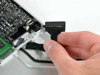
De-route the battery connector cable through the gap in the upper case and remove it from the computer.

No comments:

Post a Comment